4. Running GiftBTE
4.1 How to run
After the compiling, there is an executable file BTE_CPU under the bin folder. Run BTE_CPU in the same folder as the input folder by path of BTE_CPU (serial) or mpirun -np n path of BTE_CPU (parallel)
For example:
$ ls
- input
$ mpirun -np 4 ../../BTE_CPU
- the process0 of 4
- the process1 of 4
- the process3 of 4
- the process2 of 4
4.2 input Folder
input
├── CONTROL
├── GEOMETRY
├── PHONON
├── Other files
There are templates for the input folder in bin/examples There are three mandatory files in the input folder: CONTROL, PHONON and GEOMETRY
CONTROL
The CONTROL file determines the BTE solver to be used.
The format in the CONTROL file is
Command:
Value
Command:
Value
...
State (not mandatory):
This command determines whether the problem is steady-state or transient-state.
Value: “Transient” represents the transient, while “Steady” represents the steady state.
If it is not set, the default value is “Steady”, which means the steady-state solver is employed.
Order (not mandatory):
This command defines the spatial accuracy order.
Value: “1” represents the first order, while “2” corresponds to the second order.
If it is not set, the default value is “2”, which means the second order accuracy is employed.
The value “1” is only recommended when the solution is unstable (may happen for meshes with bad quantity).
Tref (not mandatory)
This command defines the reference temperature. The unit is Kelvin.
Value: number
If it is not set, the default value is “300”, which means that the reference temperature is 300 K.
IterativeScheme (only for steady-state, not mandatory):
This command specifies which iterative scheme for steady-state is employed.
Value: “Sequential” refers to the sequential iterative scheme (commonly adopted in discrete ordinates method), and “Synthetic” indicates the synthetic iterative scheme.
If it is not set, the default value is “Sequential”, which means the sequential iterative scheme is employed.
The value “Sequential” is suggested. The value “Synthetic” can be used when the convergence rate of iterations is too slow (near-diffusive regime).
MatrixSolver (only for steady-state, not mandatory):
This command determines the matrix solver to be utilized.
Value: “LU” denotes LU factorization and solver. “BICGSTAB” denotes Iterative method (BICGSTAB with ILU preconditioner)
If it is not set, the default value is “LU”
The value “BICGSTAB” is recommended when the memory is not enough. However, the time consumption of BICGSTAB is much larger.
MaxNumIter (only for steady-state, not mandatory):
This command sets the maximum number of iterations.
Value: Number
If it is not set, the default value is “10000”.
ResidualTemp (not mandatory):
This command establishes the convergence criterion for the lattice temperature.
Value: Number
If it is not set, the default value is “1e-6”. For complex geometries (especilly when high and localized temperature peak appears), it may be necessary to reduce the convergence criterion for the lattice temperature, such as “1e-7”.
ResidualFlux (not mandatory):
This command sets the convergence criterion for the heat flux.
Value: Number
If it is not set, the default value is “1e-4”. For complex geometries (especilly when high and localized temperature peak appears), it may be necessary to reduce the convergence criterion for the heat flux, such as “1e-5”.
TimeStep (mandatory for transient):
This command sets the duration that needs to be computed starting from the initial state of transient problem. The unit is second.
Value: Number
TotalTime (mandatory for transient):
This command sets the duration that needs to be computed starting from the initial state of transient problem. The unit is second. Value: Number
IsTDTR (not mandatory):
This command determines whether the problem is Time-domain thermoreflectance experiment (TDTR) in transient-state or not.
Value: “1” represents TDTR while “0” represents no TDTR.
If it is not set, the default value is “0”, which means not consider TDTR.
PulseTime (mandatory if IsTDTR is “1”):
This command sets the single heating time for TDTR problem.
Value: Number (should be a multiple of DeltaTime ).The unit is second.
RepetitionFrequency (mandatory for TDTR):
This command sets the repetition frequency for TDTR problem.
Value: Number. The unit is MHz.
ModulationFrequency (mandatory for TDTR):
This command sets the modulation frequency for TDTR problem.
Value: Number. The unit is MHz.
RadiusProbe (mandatory for TDTR):
This command sets the radius in the X-Y plane for TDTR problem, which is used to calculate average temperature at the top face.
Value: Number. The unit is m.
InitialTemperatureFile (not mandatory):
This command specifies the path of the initial temperature file.
Value: the path of the initial temperature file. Please see “Other files” for details.
If it is not set, the default initial temperature of all cells is the same as the reference temperature.
GEOMETRY
The GEOMETRY file provides the phonon properties
The format in the GEOMETRY file is
Command:
Value
Command:
Value
...
GeometryDimension (mandatory):
This command defines the dimensions of the computation domain.
Value: “1” denotes one dimension. “2” denotes two dimension. “3” denotes three dimension.
ScaleX (mandatory):
This command defines the scale in the x direction. The unit is “m”.
Value: Number. The default value is “1”.
ScaleY (mandatory):
This command defines the scale in the y direction. The unit is “m”.
Value: Number. The default value is “1”.
ScaleZ (mandatory):
This command defines the scale in the z direction. The unit is “m”.
Value: Number. The default value is “1”.
BCFile (mandatory):
This command specifies the path of the boundary condition file.
Value: the path of the boundary condition file. Please see “Other files” for details.
MeshType (mandatory):
This command defines the type of files.
Value: “MSH” refers to the .msh mesh file from GMSH. “COMSOL” refers to the .mphtxt file from COMSOL.
MeshFile (mandatory):
This command specifies the path of the mesh file.
Value: the path of the mesh file. Please see “Other files” for details.
HeatType (not mandatory):
This command specifies the type of heat generation file.
Value: “REGION” provides a uniform heat source in each geometry region. The format is “index of geometry \ heat source value”. “COORDINATE” provides the heat source value at each spatial point. The format is “X Y Z \ heat source value”.
HeatFile (not mandatory):
This command specifies the path of the heat source file.
Value: the path of the heat generation file. Please see “Other files” for details.
PHONON
The PHONON file provides the phonon properties
The format in the PHONON file is
Command:
Value
Command:
Value
...
MaterialNumber (mandatory):
This command defines how many kinds of materials are involved in this computation.
Value: number >=1.
BandNumber (mandatory):
This command defines how many mean free path bins are discretized in this computation.
Value: number >=1 (Suggested value: 12-15).
MaterialFile (mandatory):
This command defines the file path of the phonon properties. “ALAMODE” is used to adopt the interface with ALAMODE, which reads the phonon lifetime files from ALAMODE. “ShengBTE” is used to adopt the interface with ShengBTE, which reads BTE.omega, BTE.qpoints_ful, BTE.v, BTE.w_final, and CONTROL files from ShengBTE. “DATABASE” is used to directly read the phonon properties from the GiftBTE database.
Value: the path of the phonon properties files. Please refer to the materials folder.
(Multiple material types can be specified for different geometries. One can specify different material types as “MaterialFile 1=… MaterialFile 2=… …”, etc.)
User-defined phonon properties files can also be added into the material database (one can refer to phonon properties files in the bin/materials/DATABASE folder). Five parameters for each phonon band/mode should be specified in order in phonon properties files, i.e., group velocity, relaxation time, heat capacity, lattice ratio, and percentage of energy gained from heat sources.
GeometryMaterialType (mandatory):
This command defines the corresponding material for each geometry region in the mesh file (GEOMETRY).
Value: index of geometry index of material.
Note: the index of geometry is its index shown in COMSOL/GMESH GUI; both the index of geometry and the index of material start from “1”.
MaterialDimension (mandatory):
This command defines the material dimension.
Value: “2” is used for two-dimensional materials such as graphene. “3” is used for three-dimensional materials.
Note: the material dimension does not necessarily correlate with the geometry dimension. There is also one-dimensional geometry for three-dimensional materials (silicon thin film).
Ntheta (not mandatory):
This command defines the number of polar angles in directional discretization. Value: number>=1.
If it is not set, the default value is “4”.
Nphi (not mandatory):
This command defines the number of azimuth angles in directional discretization. Value: number>=1.
If it is not set, the default value is “4”.
(When using multiple CPU cores for computation, please make sure that Nphi × Ntheta = n × the number of CPU cores, where n is an integer.)
NOTE: the commands that are not mandatory, can be deleted or commented out using an exclamation point “!”.
Other files
(1) MeshFile
Video Links (in Chinese): GiftBTE软件教程-2:生成网格脚本
The MeshFile file provides the mesh used for computation.
For some simple geometries, Matlab/C++ scripts (mesh_generator.m/mesh_generator.cpp) are provided in the bin/mesh generator/ folder, which can generate “COMSOL” type mesh files for 1D lines, 2D square/rectangle and 3D cuboid geometries as shown below. The index of each boundary is also given, which is the BoundaryIndex in the BCFile.
1D lines:

2D square/rectangle:
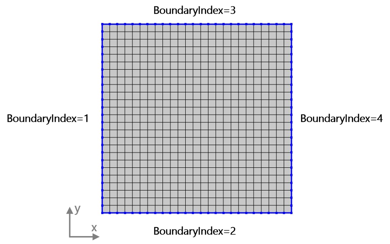
3D cuboid:
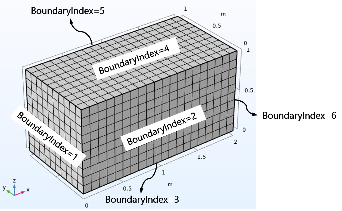
The Matlab/C++ scripts take the mesh_control file as input and generate the corresponding mesh file (inputmesh.txt). The input mesh_control file specifies the geometry dimension, length scale and the number of discrete meshes.
The format in the mesh_control file is
Command:
Value
Command:
Value
...
GeometryDimension (mandatory):
This command defines the dimensions of the computation domain.
Value: “1” represents 1D line; “2” represents 2D square/rectangle geometry; “3“ represents 3D cuboid geometry.
X_Length (mandatory):
This command defines the scale in the x direction.
Value: Number.
Y_Length (mandatory):
This command defines the scale in the y direction.
Value: Number.
Z_Length (mandatory):
This command defines the scale in the z direction.
Value: Number.
X_MeshNumber (mandatory):
This command defines the number of diecrete meshes in the x direction as shown in the figure above.
Value: Number. Y_MeshNumber (mandatory):
This command defines the number of diecrete meshes in the y direction as shown in the figure above.
Value: Number.
Z_MeshNumber (mandatory):
This command defines the number of diecrete meshes in the z direction as shown in the figure above.
Value: Number.
For other complex geometries, the COMSOL software or Gmsh open source package can be used to generate input mesh files. The MeshType in GEOMETRY should be “COMSOL” when the mesh file is built by COMSOL software (.mphtxt file) or “MSH” when the mesh file is built by Gmsh (.msh file). The mesh file can be directly exported by COMSOL software (version >= 5.5) or Gmsh (version >= 4.10).
(2) BCFile
The BCFile file provides the condition of each boundary. The format in the BCFile file should be set in the form of:
Number #Number of boundaries

#BoundaryIndex BoundaryType BoundaryValue
BoundaryIndex   BoundaryType   BoundaryValue   InterfacialFile
BoundaryIndex   BoundaryType   BoundaryValue   InterfacialFile
......
Number (mandatory):
This command gives the total number of boundaries that need to be specified. Please skip the boundaries that do not need to be specified, such as internal boundaries.
BoundaryIndex (mandatory):
This command gives the index of each boundary (starts from “1”), which is its index in the COMSOL/GMESH GUI.
BoundaryType (mandatory):
This command specifies the types of boundary conditions.
Value: “1” represents the thermalizing boundary condition, with its value being the temperature. “2” represents the diffuse boundary condition, which does not have a value. “3” represents the specular boundary condition, which also does not have a value. “5” represents the interfacial boundary condition, and InterfacialFile is the path of the file that specifies the transmittance coefficient of each phonon band. “<0”: periodic boundary condition. The BoundaryType should be “- the index of the connected boundary”. For example, if the boundary “1” and boundary “3” are a pair of periodic boundaries. The type of the “1” boundary should be “-3”, and the type of the “3” boundary should be “-1”.
BoundaryValue (mandatory):
This command sets the temperature value when BoundaryType=1 or temperature difference between two periodic boundary conditions (BoundaryType<0). Please set this command as “0” for other types of boundary conditions.
InterfacialFile (not mandatory):
This command sets the path of the file that specifies the transmittance coefficient of each phonon band when BoundaryType=5. This command is useless for other types of boundary conditions.
(3) InterfacialFile (not mandatory)
The InterfacialFile file provides transmittance coefficient of each phonon band. The format in the InterfacialFile file should be set in the form of:
Index       # matter index://start from 0
Value
Value
......

Index       # matter index:
Value
Value
......
Index: This command gives the index of the matter set in the PHONON file (start from “0”, <=”1”)
Value: This command gives the transmittance coefficient (<=1) of each phonon band from this matter to the other matter.
(4) HeatFile (not mandatory)
The HeatFile file provides distribution of heat source.
(a) HeatType = REGION
The format in the HeatFile file should be set in the form of:
Number      #Number of Geometry #GeometryIndex HeatSourceValue:
Index  Value
Index  Value
......
Number: the total number of geometry.
Index: the index of each geometry (starts from “1”).
Value: the value of uniform heat source in this geometry. The unit is “W/m^3”.
(b) HeatType = COORDINATE
The format in the HeatFile file should be set in the form of:
% Nodes:         Number
coordinateX    coordinateY   coordinateZ     Value
coordinateX    coordinateY   coordinateZ     Value
......
Number: the total number of specified heat source nodes.
coordinateX: x coordinates of each specified heat source node.
coordinateY: y coordinates of each specified heat source node (needed only when DimensionGeometry = 2 or 3).
coordinateZ: z coordinates of each specified heat source node (needed only when DimensionGeometry = 3).
Value: the value of heat source at each node. The unit is “W/m^3”.
(5) InitialTemperature (not mandatory)
The InitialTemperature file provides distribution of initial temperature. The format in the InitialTemperature file should be set in the form of:
% Nodes:         Number
coordinateX    coordinateY   coordinateZ     Value
coordinateX    coordinateY   coordinateZ     Value
......
Number: the total number of specified initial temperature nodes.
coordinateX: x coordinates of each specified initial temperature node.
coordinateY: y coordinates of each specified initial temperature node (needed only when DimensionGeometry = 2 or 3).
coordinateZ: z coordinates of each specified initial temperature node (needed only when DimensionGeometry = 3).
Value: the value of initial temperature at each node.
4.3 Output
Temperature.dat:
This file presents the temperature at the center of each cell.
The format is
X Y Z Temperature
The unit for X Y X is “m”, and is “K” for Temperature.
HeatFlux.dat:
This file provides the heat flux vector at the center of each cell.
The format is
X Y Z HeatFlux_x HeatFlux_y HeatFlux_z
The unit for X Y X is “m”, and is “W/m^2” for HeatFlux.
TempLattice.dat:
This file provides the lattice temperature at the center of each cell.
The format is
X Y Z LatticeTemperature
The unit for X Y X is “m”, and is “K” for Temperature.
Tempband.dat:
This file provides the temperature at the center of each cell for each phonon band.
The format is
PhononBandIndex X Y Z PhononBandTemperature
The unit for X Y X is “m”, and is “K” for Temperature.
Result.vtk:
This file contains temperature and heat flux values obtained from BTE in the vtu format, which can be visualized using Paraview (www.paraview.org) for graphical representation.
Temperature_macro.dat:
This file presents the temperature at the center of each cell obtained from heat diffusion equation.
The format is
X Y Z Temperature
The unit for X Y X is “m”, and is “K” for Temperature.
HeatFlux_macro.dat:
This file provides the heat flux vector at the center of each cell obtained from heat diffusion equation.
The format is
X Y Z HeatFlux_x HeatFlux_y HeatFlux_z
The unit for X Y X is “m”, and is “W/m^2” for HeatFlux.
Result_macro.vtk (only for steady-state):
This file contains temperature and heat flux values obtained from heat diffusion equation in the vtu format, which can be visualized using Paraview (www.paraview.org) for graphical representation.
TTG.dat (only for transient):
This file provides temperature change with time increasing in TTG simulation.
The format is
Time Temperature
The unit for Time is “s”, and is “K” for Temperature.
TDTR.dat (only for transient):
This file provides average temperature at top change with a time step increasing in TDTR simulation.
The format is
Timestep Temperature